|
|||||||||||||||
SmartFusion2 RTOS, CLI and FAT Demo
|
|||||||||||||||


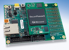
SmartFusion2 Starter Kit |
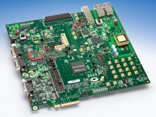
SmartFusion2 Development Kit |
Introduction
This page documents a FreeRTOS demo application for the Microsemi SmartFusion2 System-on-Chip, which integrates an ARM Cortex-M3 microcontroller into a low power non-volatile FPGA. The low cost SmartFusion2 Starter Kit and the fully featured SmartFusion2 Development Kit are both supported.The demo uses:
-
The FreeRTOS GCC ARM Cortex-M3/4 kernel port.
-
The FreeRTOS+CLI
command line interface. [Note the FreeRTOS+CLI license
is different from the FreeRTOS kernel license]
-
The FreeRTOS+FAT SL
("S"uper "L"ean) DOS compatible FAT file system. [Note the
FreeRTOS+FAT SL license
is different from the FreeRTOS kernel license]
- The Eclipse based SoftConsole software development environment.
IMPORTANT! Notes on using the FreeRTOS SmartFusion2 demo project
Please read all the following points before using this RTOS port.See also the FAQ My application does not run, what could be wrong?
Source Code Organisation
The FreeRTOS zip file contains source code for all the FreeRTOS ports and demo projects. Only a small subset of the source files are required to build this demo. See the Source Code Organization section for a description of the downloaded files and information on creating a new project.The SoftConsole Eclipse project file is located in the FreeRTOS/Demo/CORTEX_SmartFusion2_M2S050_SoftConsole" directory. Please refer to the build instructions on this page for information on preparing the project directory.
The Microsemi ARM Cortex-M3 Demo Application
Hardware and software set up
The demo presented on this page can be executed on either the SmartFusion2
Starter Kit or the SmartFusion2 Development kit.
Set up required to use the SmartFusion2 Starter Kit:
-
The FPGA itself (as opposed to the Cortex-M3 in the FPGA's Microcontroller
Sub System or MSS) must be programmed to connect GPIO 0 and GPIO 1 to the
starter kit LEDs, and UART 0 to the RS232 to USB converter. A pre-build
hardware image that can be programmed into the
FPGA using the Microsemi FlashPro software
is provided
(click the link to download the file).
Note that, at the
time of writing, the provided hardware image has only been tested on
SmartFusion2 ES parts, and on revision Rev2A of the starter kit. ES parts must be
power cycled after they have been programmed.
-
Set configBUILD_FOR_DEVELOPMENT_KIT to 0 in FreeRTOSConfig.h.
-
Ensure the settings in sys_config_mss_clocks.h
match those in sys_config_mss_clocks_starter_kit.h. Both header
files are located in the RTOSDemo_Hardware_Platform/drivers_config/sys_config
subdirectory.
Set up required to use the SmartFusion2 Development Kit:
-
The FPGA itself (as opposed to the Cortex-M3 in the FPGA's Microcontroller
Sub System or MSS) must be programmed to connect GPIO 14 and GPIO 15 to the
development kit LEDs, and UART 1 to the RS232 to USB converter. A pre-build hardware image that can be programmed into the
FPGA using the MicroSemi FlashPro software
is provided
(click the link to download the file). Note that, at the
time of writing, the provided hardware image has only been tested on
SmartFusion2 ES parts, and on Development Kit revision B. ES parts must be
power cycled after they have been programmed.
-
Set configBUILD_FOR_DEVELOPMENT_KIT to 1 in FreeRTOSConfig.h.
-
Ensure the settings in sys_config_mss_clocks.h
match those in sys_config_mss_clocks_development_kit.h. Both header
files are located in the RTOSDemo_Hardware_Platform/drivers_config/sys_config
subdirectory.
Functionality
By setting configCREATE_SIMPLE_BLINKY_DEMO_ONLY in FreeRTOSConfig.h the demo can be configured to run either a simply blinky example, or a comprehensive demo application.
Functionality with configCREATE_SIMPLE_BLINKY_DEMO_ONLY set to 1
If configCREATE_SIMPLE_BLINKY_DEMO_ONLY is set to 1 then main() will call main_blinky(). main_blinky() creates a very simple demo that includes two tasks and one queue. One task repeatedly sends a message on the queue to the other task, which toggles an LED each time the message is received. The message is sent every 200 milliseconds, so when executing correctly a single LED will toggle every 200 milliseconds.
Functionality with configCREATE_SIMPLE_BLINKY_DEMO_ONLY set to 0
If configCREATE_SIMPLE_BLINKY_DEMO_ONLY is set to 0 then main() will call main_full(). main_full() creates a comprehensive test and demo application that demonstrates:- The FreeRTOS+CLI command line interface. [Note the FreeRTOS+CLI license is different from the FreeRTOS kernel license]
- The FreeRTOS+FAT SL ("S"uper "L"ean) DOS compatible FAT file system. [Note the FreeRTOS+FAT SL license is different from the FreeRTOS kernel license]
- Software timers.
- Queues.
- Mutexes.
- Semaphores.
- A simple interrupt service routine that causes an RTOS task context switch.
 FreeRTOS+CLI is used to, among other things, access a set of example files created on a RAM disk by
FreeRTOS+FAT SL. As always typing "help" in the CLI will generate a list of
available commands (commands that have been registered with FreeRTOS+CLI by the
demo application). Both the files created and the file system related CLI commands
are (at the time of writing) identical to those used by the FreeRTOS+FAT SL
Win32 simulator demo. See the
Win32 simulator demo documentation
page for details.
FreeRTOS+CLI is used to, among other things, access a set of example files created on a RAM disk by
FreeRTOS+FAT SL. As always typing "help" in the CLI will generate a list of
available commands (commands that have been registered with FreeRTOS+CLI by the
demo application). Both the files created and the file system related CLI commands
are (at the time of writing) identical to those used by the FreeRTOS+FAT SL
Win32 simulator demo. See the
Win32 simulator demo documentation
page for details.
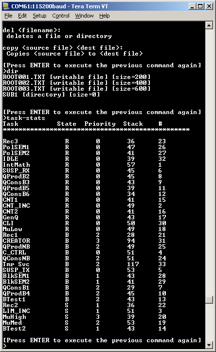
FreeRTOS+CLI is accessed through a virtual COM port that will enumerate when the SmartFusion2 Starter Kit or SmartFusion2 Development kit is connected by the USB port marked P1 (Starter Kit) or J24 (Development Kit) to the host computer. Once enumerated the virtual COM will appear as a standard COM port, allowing access to the CLI through a standard dumb terminal program such as HyperTerminal or TeraTerm. The image on the right shows a sample CLI session using TeraTerm. 115200 baud is used in the hardware. Note the Development Kit enumerates 4 separate virtual COM ports - attempt to connect through the highest numbered of the 4 first.
Most of the other created tasks are from the set of standard demo tasks that are used by all FreeRTOS demo applications. The standard demo tasks have no specific functionality or purpose other than to demonstrate the FreeRTOS API being used and test the RTOS kernel port.
A 'check' software timer is created that periodically inspects the standard demo tasks to ensure all the tasks are functioning as expected. The check software timer's callback function toggles an LED to give visual feedback of the demo status. If an LED toggles every 3 seconds, then the check software timer has not discovered any problems. If the rate at which the LED toggles increases to every 200 milliseconds, then the check software timer is indicating that an issue has been reported by at least one standard demo task. Another LED will also toggle with a fixed 333 millisecond period. This second LED is under the control of a standard demo "flash" software timer.
Building and executing the demo application
- Ensure the hardware and software is set up to target either the SmartFusion2 Starter Kit or the SmartFusion2 Development kit as described above.
- NOTE: The CreateProjectDirectoryStructure.bat batch file must be executed before the project is imported into a SoftConsole Eclipse workspace. The batch file is located in the same directory as the project files. FreeRTOSConfig.h contains a #error directive that can be commented out after the batch file has been executed.
- Open SoftConsole and either create a new workspace or select an existing workspace when prompted.
- Select "Import" from the IDE's "File" menu to bring up the import dialog box.
-
In the Import dialog box, select "General->Existing Projects Into Workspace"
then browse to and select the FreeRTOS/Demo/CORTEX_SmartFusion2_M2S050_SoftConsole
directory. Two projects will be visible. "RTOSDemo" is the demo application.
"RTOSDemo_Hardware_Platform" is a board support package library. Check
(select) both projects then click "Finish".
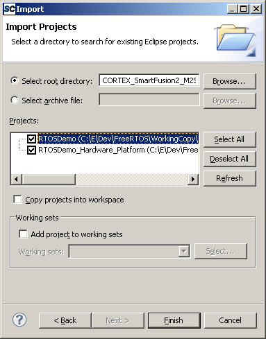
Import both projects into the Eclipse workspace - Open FreeRTOSConfig.h and set configCREATE_SIMPLE_BLINKY_DEMO_ONLY to generate either the simply blinky demo, or the full test and demo application, as required.
- Ensure the target hardware is connected to the host computer using the FlashPro4 interface that is supplied with both the Starter and Development kits.
- Select "Build All" from the IDE's "Project" menu, both projects should build without any errors or warnings.
-
After the build completes, select "Debug Configurations..." from the
IDE's "Debug" menu, and configure a debug configuration as shown below
before clicking "Debug" (the debug configuration fields may be filled
in automatically).
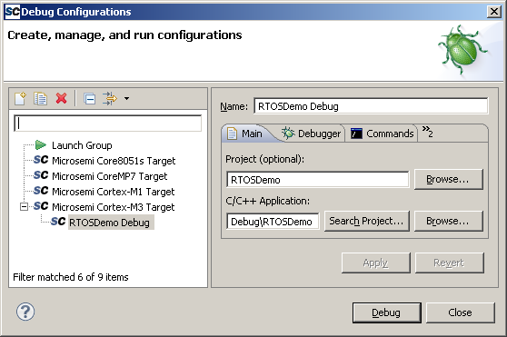
The Eclipse debug configuration
RTOS Configuration and Usage Details
ARM Cortex-M3 FreeRTOS port specific configuration
Configuration items specific to this demo are contained in FreeRTOS/Demo/CORTEX_SmartFusion2_M2S050_SoftConsole/RTOSDemo/FreeRTOSConfig.h. The constants defined in this file can be edited to suit your application. In particular --
configTICK_RATE_HZ
This sets the frequency of the RTOS tick interrupt. The supplied value of 1000Hz is useful for testing the RTOS kernel functionality but is faster than most applications need. Lowering the frequency will improve efficiency.
-
configKERNEL_INTERRUPT_PRIORITY and configMAX_SYSCALL_INTERRUPT_PRIORITY
See the RTOS kernel configuration documentation for full information on these configuration constants.
-
configLIBRARY_LOWEST_INTERRUPT_PRIORITY and configLIBRARY_MAX_SYSCALL_INTERRUPT_PRIORITY
Whereas configKERNEL_INTERRUPT_PRIORITY and configMAX_SYSCALL_INTERRUPT_PRIORITY are full eight bit shifted values, defined to be used as raw numbers directly in the ARM Cortex-M3 NVIC registers, configLIBRARY_LOWEST_INTERRUPT_PRIORITY and configLIBRARY_MAX_SYSCALL_INTERRUPT_PRIORITY are equivalents that are defined using just the 4 priority bits implemented in the SmartFusion2 NVIC. These values are provided because the CMSIS library function NVIC_SetPriority() requires the un-shifted 4 bit format.
Attention please!: See the page dedicated to setting interrupt priorities on ARM Cortex-M devices. Remember that ARM Cortex-M cores use numerically low priority numbers to represent HIGH priority interrupts. This can seem counter-intuitive and is easy to forget! If you wish to assign an interrupt a low priority do NOT assign it a priority of 0 (or other low numeric value) as this will result in the interrupt actually having the highest priority in the system - and therefore potentially make your system crash if this priority is above configMAX_SYSCALL_INTERRUPT_PRIORITY. Also, do not leave interrupt priorities unassigned, as by default they will have a priority of 0 and therefore the highest priority possible.
The lowest priority on a ARM Cortex-M core is in fact 255 - however different ARM Cortex-M microcontroller manufacturers implement a different number of priority bits and supply library functions that expect priorities to be specified in different ways. For example, on Microsemi SmartFusion2 SoC Cortex-M3 cores, the lowest priority you can specify is in fact 15 - this is defined by the constant configLIBRARY_LOWEST_INTERRUPT_PRIORITY in FreeRTOSConfig.h. The highest priority that can be assigned is always zero.
It is also recommended to ensure that all priority bits are assigned as being preemption priority bits, and none as sub priority bits, as they are in the provided demo.
Each port #defines 'BaseType_t' to equal the most efficient data type for that processor. This port defines BaseType_t to be of type long.
Interrupt service routines
Unlike many FreeRTOS ports, interrupt service routines that cause a context switch have no special requirements, and can be written as per the compiler documentation. The macros portEND_SWITCHING_ISR() (or portYIELD_FROM_ISR()) can be used to request a context switch from within an interrupt service routine.Note that portEND_SWITCHING_ISR() will leave interrupts enabled.
The following source code snippet is provided as an example. The interrupt uses a semaphore to synchronise with a task (not shown), and calls portEND_SWITCHING_ISR to ensure the interrupt returns directly to the task. See the function prvUARTRxNotificationHandler() in the file UARTCommandConsole.c included in this demo project for another example.
void Dummy_IRQHandler(void)
{
long lHigherPriorityTaskWoken = pdFALSE;

    /* Clear the interrupt if necessary. */
    Dummy_ClearITPendingBit();

    /* This interrupt does nothing more than demonstrate how to synchronise a
    task with an interrupt.  A semaphore is used for this purpose.  Note
    lHigherPriorityTaskWoken is initialised to zero. */
    xSemaphoreGiveFromISR( xTestSemaphore, &lHigherPriorityTaskWoken );

    /* If there was a task that was blocked on the semaphore, and giving the
    semaphore caused the task to unblock, and the unblocked task has a priority
    higher than the current Running state task (the task that this interrupt
    interrupted), then lHigherPriorityTaskWoken will have been set to pdTRUE
    internally within xSemaphoreGiveFromISR().  Passing pdTRUE into the
    portEND_SWITCHING_ISR() macro will result in a context switch being pended to
    ensure this interrupt returns directly to the unblocked, higher priority,
    task.  Passing pdFALSE into portEND_SWITCHING_ISR() has no effect. */
    portEND_SWITCHING_ISR( lHigherPriorityTaskWoken );
}
Only FreeRTOS API functions that end in "FromISR" can be called from an interrupt service routine - and then only if the priority of the interrupt is less than or equal to that set by the configMAX_SYSCALL_INTERRUPT_PRIORITY configuration constant (or configLIBRARY_MAX_SYSCALL_INTERRUPT_PRIORITY).
Resources used by FreeRTOS
FreeRTOS requires exclusive use of the SysTick and PendSV interrupts. SVC number #0 is also used.Switching between the pre-emptive and co-operative RTOS kernels
Set the definition configUSE_PREEMPTION within FreeRTOSConfig.h to 1 to use pre-emption or 0 to use co-operative. The full demo application may not execute correctly when the co-operative RTOS scheduler is selected.Memory allocation
Source/Portable/MemMang/heap_4.c is included in the ARM Cortex-M3 demo application project to provide the memory allocation required by the RTOS kernel. Please refer to the Memory Management section of the API documentation for full information.Miscellaneous
Note that vPortEndScheduler() has not been implemented.
NXP tweet showing LPC5500 (ARMv8-M Cortex-M33) running FreeRTOS.
Meet Richard Barry and learn about running FreeRTOS on RISC-V at FOSDEM 2019
Version 10.1.1 of the FreeRTOS kernel is available for immediate download. MIT licensed.
View a recording of the "OTA Update Security and Reliability" webinar, presented by TI and AWS.
FreeRTOS and other embedded software careers at AWS.

![]()


![]()