Microchip PICmicro (PIC18) RTOS Port
For the MPLAB C18 compiler
[RTOS Ports]
There are currently two ports for the Microchip PICMicro PIC18 series of embedded microcontrollers. This page relates only to the
port using the MPLAB C18 compiler.
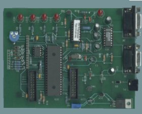
The PICMicro PIC18 RTOS port was developed on a 40 pin PICmicro prototyping board from
Forest Electronic Developments (FED) (instructions are provided should you wish to use an alternative development board).
A PIC18F452
microcontroller was installed. This prototyping board allows for in system flash programming by means of the PICPROG
utility, also supplied by FED.
The MPLAB C18 development tools
were used, along with the MPLAB IDE
front end. The real time simulator included with the MPLAB development tools download was utilised for debugging.
Unfortunately the compiler is not free or open source, and there does not seem to be a suitable open source alternative.
The IDE and simulator are however free, and the development tools can be downloaded with a generous evaluation period. A
limited functionality student version is also available.
IMPORTANT! Notes on using the PICMicro MPLAB RTOS port
Please read all the following points before using this RTOS port.
- Source Code Organization
- The Demo Application
- Configuration and Usage Details
See also the FAQ My application does not run, what could be wrong?
Source Code Organization
The FreeRTOS download contains the source code for all the FreeRTOS ports.
See the Source Code Organization section for a description of the
downloaded files and information on creating a new project.
The MPLAB PIC18 demo application project files are located in the Demo/PIC18_MPLAB directory.
The Demo Application
Unlike the RTOS demo applications supplied with the other ports, the PICMicro PIC18 RTOS demo is split into several smaller programs.
This enables the demo's to be executed on the RAM challenged 40 pin devices. The 64 and 80 pin devices would have required a
more costly prototyping board. All three RTOS demo applications are included within one workspace called RTOSDemo.mcw which
can be opened from within the MPLAB IDE.
Demo application projects
The demo application workspace includes the following three projects.
- RTOSDemo1
Includes the standard minimal "integer" and "pollQ" tasks, along with a "check" task that periodically checks the other
tasks are operating without error, and flashes an LED accordingly. To ensure the target is not unexpectedly resetting
a single "X" is transmitted from the USART when the application boots. When operating correctly RTOSDemo1 will
cause LED 1 to toggle every second. If an error has occurred in any task the toggle rate will increase to 100ms.
- RTOSDemo2
Includes the standard minimal "flash" tasks, along with a modified version of the "integer" task. To ensure the target is not unexpectedly resetting
a single "X" is transmitted from the USART when the application boots. When operating correctly RTOSDemo2 will
cause LED 1 to toggle every 333ms, LED 2 every 666ms and LED 3 every 999ms. LED 4 will only be permanently lit should
the integer task encounter an error.
- RTOSDemo3
Includes the standard minimal "comtest" and minimal "integer" tasks, along with a check task. This demo
tests the context switch from within an ISR and requires a loopback connector to be placed on J2 (i.e. pins 2 and
3 must be shorted together on the serial port). To ensure the target is not unexpectedly resetting, LED 1 is lit for 500ms
when the application boots. When operating correctly RTOSDemo3 will toggle LED 3 every time a character is transmitted
and LED 4 every time a character is received, LED 2 will toggle every second (a 100ms toggle indicates an error), and
LED 1 will remain off after the initial 500ms flash.
See the demo application section for more information on the standard
demo application files.
Building an RTOS demo application
The RTOS demo application project files contain absolute path definitions. If anybody can get
around this problem then please let me know how! To use the project files on your system it is likely the paths will
require modification. This is easiest to achieve by opening the RTOSDemo1.mcp, RTOSDemo2.mcp and RTOSDemo3.mcp files
in a text editor and editing as necessary. Search for the string "e:\dev" to find the lines that require
modification.
- With the workspace open in MPLAB IDE, select the project you wish to build by right clicking on the project name in
the project window and selecting "Set as Active Project" from the resulting pop up menu.
- Select "Build all" from the MPLAB IDE Project menu. RTOSDemo1.hex, RTOSDemo2.hex or RTOSDemo3.hex will be output
depending on the selected project within the workspace.
Programming the PICMicro PIC18
The prototyping board is programmed using the PICPROG utility supplied by FED. PICPROG can open intel HEX and binary files.
I have however found more often than not that HEX files are not recognized correctly (some incompatibility between HEX
file formats?). When a file is opened and viewed from within PICPROG, the first byte should be E7(HEX) - a
GOTO instruction. If this is not the case, convert the HEX file to a binary and open it as such (instruction follow).
- Ensure your host computer is connected to the FED prototyping board, and the prototyping board is powered up,
then start PICPROG.
- Build the required RTOS demo application as described above.
- Download HEX2BIN and place it within your path.
- Open a command prompt and navigate to the Demo/PIC18_MPLAB directory.
- Run the MakeBin1.bat, MakeBin2.bat or MakeBin3.bat, depending on which demo you have built. This will convert the
created HEX file into a file called RTOSDemo.bin. Note the same .bin output file name is used whichever hex file is converted.
- In PICPROG, select "Clear Buffer" from the file menu then open the created RTOSDemo.bin file.
- Ensure the config fuses are set as shown below. Sometimes these values are retained, and sometime they are not. If
the fuses are not set correctly, double click on the word "Fuses" and set them as shown. This ensures, amongst other things,
that the watchdog is not enabled.

- Click the "Write Device" speed button (the one with the hand icon).
Memory areas used by the compiler
The MPLAB compiler does not generate reentrant code. In particular it uses memory areas as scratch memory when
performing mathematical operations. These memory areas are saved by the RTOS kernel as part of the context of each task to ensure
re-entrancy. The amount of RAM saved within the context of a task is set by the macro portCOMPILER_MANAGED_MEMORY_SIZE
within Source/portable/MPLAB/PIC18F/port.c.
After building an application, check the size of the .tmpdata and MATH_DATA sections within the map file. If these total more than 19
bytes the constant portCOMPILER_MANAGED_MEMORY_SIZE and the macros portSAVE_CONTEXT and portRESTORE_CONTEXT
will have to be modified accordingly. It is not clear whether this data block will always be of fixed size, or be
application specific.
Memory allocation
Source/Portable/MemMang/heap_1.c is included in the PICMicro demo application projects to provide the memory allocation required
by the real time kernel.
Please refer to the Memory Management section of the API documentation for
full information.
Linker scripts
The linker script provided with the demo application creates a large memory area to hold the heap defined within the
heap_1.c file. This arrangement is effective for the demo applications.
The MPLAB development tools have the following restriction as described by the linker manual:"You must not combine
data memory regions when using MPLINK Linker with MPLAB C18 C compiler. MPLAB C18 requires that any section be located
within a single bank.". Depending on the memory requirements of user applications it might be that this restriction
is violated. John Franklin has kindly provided an example of how this situation can be avoided, should the need arise.
Johns example files, along with a pdf file containing more detailed information,
can be obtained here.
Development tools options
As with all the ports, it is essential that the correct compiler options are used. The best way to ensure this is to base your
application on the provided demo application project.
RTOS port specific configuration
Configuration items specific to this port are contained in Demo/PIC18_MPLAB/FreeRTOSConfig.h.
The constants defined in
this file can be edited to suit your application. In particular - the definition configTICK_RATE_HZ is used to set the frequency
of the RTOS tick. The supplied value of 1000Hz is useful for testing the RTOS kernel functionality but is faster than most applications
Each port #defines 'BaseType_t' to equal the most efficient data type for that processor. This port defines
BaseType_t to be of type char.
Switching between the pre-emptive and co-operative RTOS kernels
Set the definition configUSE_PREEMPTION within Demo/PIC18_MPLAB/FreeRTOSConfig.h to 1 to use pre-emption or 0
to use co-operative.
Demo application serial port driver
The supplied serial port drivers are written to test some of the RTOS kernel features - and they are not
intended to represent an optimised solution.
Using the MPLAB simulator
When using the MPLAB IDE simulator, check to ensure the watchdog is disabled by using the "Configuration Bits" option on the
MPLAB IDE Configuration menu. Also, remember to clear the file registers between each execution. This is done using
the Debugger->Clear Memory menu item within MPLAB IDE.
Using an alternative PICMicro PIC18 device
- To run the demo applications a microcontroller must provide at least as much RAM as the PIC18F452.
- The linker script file for the chosen device must be modified to provide a memory block large enough to contain the memory pools
defined within heap_1.c. The linker script included in the demo application projects shows how this can be achieved.
- Peripherals accessed by the RTOS port and RTOS demo application use the constants defined within the MPLAB PIC18
compiler header files. This ensures
portability between devices. Using an alternative device may however necessitate the utilization of a different timer and CCP
peripheral to generate the RTOS kernel ticks. The timer setup is contained within prvSetupTimerInterrupt() which is in
the PICMicro PIC18 specific port.c file.
Using an alternative hardware platform
The FED prototyping board was chosen for its low cost, but it should be easy to port the demo applications to an alternative platform.
- It is very unlikely that an alternative board would have LEDs connected in the same configuration as the
FED demo board. The LED routines are contained within Demo/PIC18_MPLAB/ParTest/ParTest.c and will require modification.
Copyright (C) Amazon Web Services, Inc. or its affiliates. All rights reserved.
|