|
|||||||||||||||
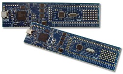
NXP LPC1114 ARM Cortex-M0 Demo
|
|||||||||||||||


 |
Introduction
The project described on this page demonstrates the FreeRTOS ARM Cortex-M0 GCC port. It is configured to run on the LPC1114 version of the LPCXpresso board, using the free Eclipse based LPCXpresso IDE.Using a compile time option (described below), the project can be configured to either create a basic blinky style demo, or a more comprehensive test and demo application that includes tasks that exercise the interrupt nesting behaviour.
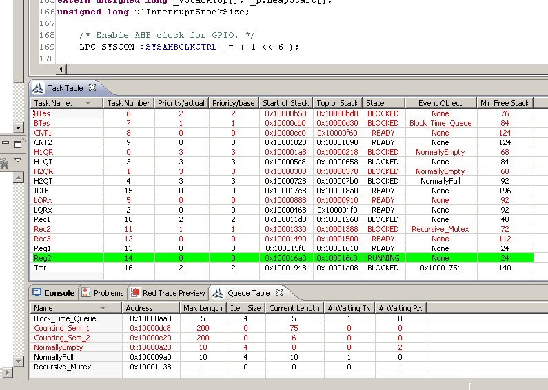
Screen shot of the FreeRTOS aware state viewer
plug-in that ships with the LPCXpresso IDE as
standard. Click the image to enlarge.
IMPORTANT! Notes on using the LPC1114 LPCXpresso ARM Cortex-M0 Demo
Please read all the following points before using this RTOS port.See also the FAQ My application does not run, what could be wrong?
Source Code Organisation
The FreeRTOS download contains the source code for all the FreeRTOS ports, so includes many more files than are needed by this demo. See the Source Code Organization section for a description of the downloaded files and information on creating a new project.The FreeRTOS demo application is dependent on the CMSIS library, which is provided as a separate LPCXpresso project. The demo application project and the CMSIS project must both be imported into an LPCXpresso workspace. Both projects are located in subdirectories of the FreeRTOS/Demo/CORTEX_M0_LPC1114_LPCXpresso directory, and can be imported into LPCXpresso together. The Preparing the Eclipse Project section below contains important information on setting up the demo project directory, and importing the demo project into the LPCXpresso IDE.
The Demo Application
Demo application hardware set up
The demo uses the LED that is integrated onto the LPCXpresso board, so no hardware setup is required.
Preparing the Eclipse project directory
Eclipse projects can be either standard makefile projects, or managed make projects.
The FreeRTOS LPCXpresso ARM Cortex-M0 project uses a managed make project. This in
turn means that either:
- All the source files needed to build the project must be located under the folder/directory that contains the project file itself, or
- The Eclipse workspace (note workspace, not project) needs to be configured to locate the files elsewhere on the hard disk.
CreateProjectDirectoryStructure.bat must be executed before the LPCXpresso project is imported into the Eclipse workspace.
CreateProjectDirectoryStructure.bat cannot be executed from within the LPCXpresso IDE.
Importing the demo application and CMSIS projects into the LPCXpresso Eclipse workspace
To import the necessary projects into an existing or new Eclipse Workspace:-
Select "Import" from the LPCXpresso "File" menu. The dialogue box shown below
will appear. Select "Existing Projects into Workspace".
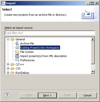
The dialogue box that appears when "Import" is first clicked
-
In the next dialogue box, select FreeRTOS/Demo/CORTEX_M0_LPC1114_LPCXpresso
as the root directory. Then, make sure that both the RTOSDemo and CMSISv2p00_LPC11xx
projects are checked in the "Projects" area, and that the Copy Projects Into
Workspace box is not checked, before clicking
the Finish button (see the image below for the correct check box states).
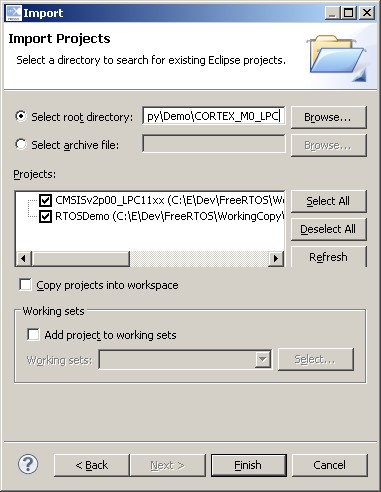
Make sure both projects are checked, and "Copy projects into workspace" is not checked
Building and running the demo application
The single RTOSDemo project provides two configurations. It can be configured as a simple blinky style project, or a more comprehensive test and demo application. The mainCREATE_SIMPLE_BLINKY_DEMO_ONLY setting in main.c is used to select between the two. Set mainCREATE_SIMPLE_BLINKY_DEMO_ONLY to one to create the basic Blinky style demo. Set mainCREATE_SIMPLE_BLINKY_DEMO_ONLY to 0 to create the more comprehensive test and demo application.- Set the mainCREATE_SIMPLE_BLINKY_DEMO_ONLY constant to generate the required demo functionality, as noted above.
- Connect the LPCXpresso LPC1114 board to your host computer using a standard USB cable. You may be prompted to install some USB drivers.
- Ensure that CreateProjectDirectoryStructure.bat has been executed, and that the project has been correctly imported into the Eclipse workspace.
- Select 'Build All' from the IDE's 'Project' menu, both the CMSIS and RTOSDemo projects should build without any errors or warnings.
- Start a debug session by either pressing the 'Debug' speed button, or selecting "Debug 'RTOSDemo'" in the IDE's quick start panel. The microcontroller flash memory will be programmed, and the debugger will break on entry to the main() function.
Functionality with mainCREATE_SIMPLE_BLINKY_DEMO_ONLY set to 1
Setting mainCREATE_SIMPLE_BLINKY_DEMO_ONLY to 1 results in main() calling main_blinky(). main_blinky() sets up a very simple demo, as described below.-
The main_blinky() Function:
main_blinky() creates one queue, and two tasks. It then starts the scheduler.
-
The Queue Send Task:
The queue send task is implemented by the prvQueueSendTask() function in main_blinky.c. prvQueueSendTask() sits in a loop that causes it to repeatedly block for 200 milliseconds, before sending the value 100 to the queue that was created within main_blinky(). Once the value is sent, the task loops back around to block for another 200 milliseconds.
-
The Queue Receive Task:
The queue receive task is implemented by the prvQueueReceiveTask() function in main_blinky.c. prvQueueReceiveTask() sits in a loop where it repeatedly blocks on attempts to read data from the queue that was created within main_blinky(). When data is received, the task checks the value of the data, and if the value equals the expected 100, toggles the LED. The 'block time' parameter passed to the queue receive function specifies that the task should be held in the Blocked state indefinitely to wait for data to be available on the queue. The queue receive task will only leave the Blocked state when the queue send task writes to the queue. As the queue send task writes to the queue every 200 milliseconds, the queue receive task leaves the Blocked state every 200 milliseconds, and therefore toggles the LED every 200 milliseconds.
Functionality with mainCREATE_SIMPLE_BLINKY_DEMO_ONLY set to 0
Setting mainCREATE_SIMPLE_BLINKY_DEMO_ONLY to 0 results in main() calling main_full(). main_full() sets up a more comprehensive test and demo application, as described below.-
The main_full() Function:
main_full() creates a set of standard demo tasks (including a set of tasks that test the interrupt nesting behaviour), some application specific test tasks, and a timer. It then starts the scheduler.
-
The "Reg Test" Tasks:
These fill the registers with known values, then check that each register maintains its expected value for the lifetime of the task. Each task uses a different set of values. The reg test tasks execute with a very low priority, so get preempted very frequently. A register containing an unexpected value is indicative of an error in the context switching mechanism.
-
The "Check" software Timer:
The check software timer period is initially set to three seconds. Its callback function checks that all the standard demo tasks, and the register check tasks, are not only still executing, but are executing without reporting any errors. If the check timer callback discovers that a task has either stalled, or reported an error, then it changes the period of the check timer from the initial three seconds, to just 200ms. The callback function also toggles the LED each time it is called. This provides a visual indication of the system status: If the LED toggles every three seconds, then no issues have been discovered. If the LED toggles every 200ms, then an issue has been discovered with at least one task.
RTOS Configuration and Usage Details
Interrupt service routines
Interrupt service routines that cause a context switch have no special requirements. The macro portEND_SWITCHING_ISR() can be used to request a context switch from within an ISR.Note that portEND_SWITCHING_ISR() will leave interrupts enabled.
The interrupt nesting test tasks require that two timers are configured to generate interrupts. The interrupt service routines are defined in IntQueueTimer.c, and can be used as examples for application writers. They do not, however, directly demonstrate the use of FreeRTOS safe API functions (those that end in "FromISR"). Therefore, a dummy interrupt implementation called Dummy_IRQHandler() is provided at the end of main.c, and duplicated below.
void Dummy_IRQHandler(void)
{
long lHigherPriorityTaskWoken = pdFALSE;

    /* Clear the interrupt if necessary. */
    Dummy_ClearITPendingBit();

    /* This interrupt does nothing more than demonstrate how to synchronise a
    task with an interrupt.  A semaphore is used for this purpose.  Note
    lHigherPriorityTaskWoken is initialised to zero.  Only FreeRTOS API functions
	that end in "FromISR" can be called from an ISR. */
    xSemaphoreGiveFromISR( xTestSemaphore, &lHigherPriorityTaskWoken );

    /* If there was a task that was blocked on the semaphore, and giving the
    semaphore caused the task to unblock, and the unblocked task has a priority
    higher than the current Running state task (the task that this interrupt
    interrupted), then lHigherPriorityTaskWoken will have been set to pdTRUE
    internally within xSemaphoreGiveFromISR().  Passing pdTRUE into the
    portEND_SWITCHING_ISR() macro will result in a context switch being pended to
    ensure this interrupt returns directly to the unblocked, higher priority,
    task.  Passing pdFALSE into portEND_SWITCHING_ISR() has no effect. */
    portEND_SWITCHING_ISR( lHigherPriorityTaskWoken );
}
Note that the following lines are included in FreeRTOSConfig.h.
	#define vPortSVCHandler      SVC_Handler
	#define xPortPendSVHandler   PendSV_Handler
	#define xPortSysTickHandler  SysTick_Handler
These definitions map the FreeRTOS kernel interrupt handler function names onto the CMSIS interrupt handler functions names (or at least whatever is used in the unmodified vector table supplied by the compiler) - and in so doing, allow the Code Red provided linker script and start up files to be used without modification.
Attention please!: See the page dedicated to setting interrupt priorities on ARM Cortex-M devices. Remember that ARM Cortex-M cores use numerically low priority numbers to represent HIGH priority interrupts. This can seem counter-intuitive and is easy to forget! If you wish to assign an interrupt a low priority do NOT assign it a priority of 0 (or other low numeric value) as this will result in the interrupt actually having the highest priority in the system. Also, do not leave interrupt priorities unassigned, as by default they will have a priority of 0 and therefore the highest priority possible.
RTOS port specific configuration
Configuration items specific to these demos are contained in FreeRTOS/Demo/CORTEX_M0_LPC1114_LPCXpresso/RTOSDemo/Source/FreeRTOSConfig.h. The constants defined in FreeRTOSConfig.h can be edited to meet the needs of your application. In particular -- configTICK_RATE_HZ
This sets the frequency of the RTOS tick interrupt. The supplied value of 1000Hz is useful for testing the RTOS kernel functionality, but is faster than most applications require. Lowering this value will improve efficiency.
Each port #defines 'BaseType_t' to equal the most efficient data type for that processor. This port defines BaseType_t to be of type long.
Note that vPortEndScheduler() has not been implemented.
Switching between the pre-emptive and co-operative RTOS kernels
Set the definition configUSE_PREEMPTION within FreeRTOS/Demo/CORTEX_M0_LPC1114_LPCXpresso/RTOSDemo/Source/FreeRTOSConfig.h to 1 to use pre-emption or 0 to use co-operative.Memory allocation
Source/Portable/MemMang/heap_1.c is included in the ARM Cortex-M0 demo application project to provide the memory allocation required by the RTOS kernel. Please refer to the Memory Management section of the API documentation for full information.
NXP tweet showing LPC5500 (ARMv8-M Cortex-M33) running FreeRTOS.
Meet Richard Barry and learn about running FreeRTOS on RISC-V at FOSDEM 2019
Version 10.1.1 of the FreeRTOS kernel is available for immediate download. MIT licensed.
View a recording of the "OTA Update Security and Reliability" webinar, presented by TI and AWS.
FreeRTOS and other embedded software careers at AWS.

![]()


![]()