|
|
|
|
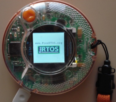
This page describes the FreeRTOS demo application for the STM32 Primer - a novel evaluation platform for the STMicroelectronics STM32 ARM Cortex-M3 microcontroller. The demo uses the GCC compiler with the Raisonance Ride V7 IDE.
The demo utilises drivers and other source files from CircleOS (which, unlike FreeRTOS.org, is not a real time kernel). These files are licensed separately from FreeRTOS.org. Users must familiarise themselves with the CircleOS license. Please note that the FreeRTOS demo is not itself a CircleOS application and will overwrite CircleOS on the STM32 Primer. The batch files located in the [Program Files]\Raisonance\Ride\Lib\ARM\CircleOS directory of your Raisonance Ride distribution can be used to restore CircleOS to the STM32 Primer hardware.
Using RIDE version 7: FreeRTOS V5.1.1 will not build with the latest versions of the RIDE libraries. The head revision in the FreeRTOS SVN repository has already been fixed - the necessary changes will be included in the next release.
Upgrading to FreeRTOS V5.0.3: FreeRTOS V5.0.3 introduced the configMAX_SYSCALL_INTERRUPT_PRIORITY configuration option to the ARM Cortex-M3 port. See the RTOS kernel configuration documentation for full information on this feature.
Upgrading to FreeRTOS V4.8.0: Prior to V4.8.0 the FreeRTOS kernel did not make use of the SVCall interrupt. From V4.8.0 onwards it does. Therefore, to upgrade an older project to the V4.8.0 standard, a small edit to the startup code is required. To do this, simply install vPortSVCHandler() in the SVCall position within the interrupt vector table (contained in the startup source file). The demo projects included in the FreeRTOS download have already been updated so these can be used as an example.
See also the FAQ My application does not run, what could be wrong?
The Ride workspace file for the STM32F103 Primer Ride demo is called RTOSDemo.rprj and is located in the FreeRTOS\Demo\CORTEX_STM32F103_Primer_GCC directory.
A USB interface is used to connect directly between the STM32 Primer and the host PC.
The following tasks and tests are created in addition to the standard demo tasks:
A high frequency periodic interrupt is generated using a free running timer to demonstrate the use of the 'configKERNEL_INTERRUPT_PRIORITY' configuration constant. The interrupt service routine measures the number of processor clocks that occur between each interrupt - and in so doing measures the jitter in the interrupt timing. The maximum measured jitter time is latched in the ulMaxJitter variable, and displayed on the LCD display by the 'Check' task as described below. The fast interrupt is configured and handled in the timertest.c source file. This demonstrates how the RTOS kernel can be configured so as to have no impact on higher priority interrupt processing.
The ARM Cortex-M3 core has the ability to hasten the entry into an interrupt service routine (and therefore reduce latency) by up to 8 cycles should a high priority interrupt occur while a lower priority interrupt is already being serviced. The measured jitter time should therefore be no more than 8 clock cycles.
The LCD task is a 'gatekeeper' task. It is the only task that is permitted to access the display directly. Other tasks wishing to write a message to the LCD send the message on a queue to the LCD task instead of accessing the LCD themselves. The LCD task just blocks on the queue waiting for messages - waking when messages arrive.
Two types of message are received by the LCD task. The first type contain strings for display on the LCD. The second type contains an instruction to update the LCD in accordance with the current MEMS input as described below (the MEMS functionality is from the CircleOS demo).
This only executes every five seconds but has the highest priority so is guaranteed to get processor time. Its main function is to check that all the standard demo tasks are still operational. Should any unexpected behaviour within a demo task be discovered the 'check' task will write an error to the LCD (via the LCD task). If all the demo tasks are executing with their expected behaviour then the check task writes PASS along with the max jitter time to the LCD (again via the LCD task), as described above.
This is a basic Tick Hook that periodically sends a message to the LCD task to request that the MEMS input be updated.
This is a very basic task that does nothing but wake every second, then flash an LED. It is used for timing validation only.
When executing correctly the demo application will behave as follows:
This sets the frequency of the RTOS tick. The supplied value of 1000Hz is useful for testing the RTOS kernel functionality but is faster than most applications require. Lowering this value will improve efficiency.
See the RTOS kernel configuration documentation for full information on these configuration constants.
Attention please!: Remember that ARM Cortex-M3 cores use numerically low priority numbers to represent HIGH priority interrupts, which can seem counter-intuitive and is easy to forget! If you wish to assign an interrupt a low priority do NOT assign it a priority of 0 (or other low numeric value) as this can result in the interrupt actually having the highest priority in the system - and therefore potentially make your system crash if this priority is above configMAX_SYSCALL_INTERRUPT_PRIORITY.
The lowest priority on a ARM Cortex-M3 core is in fact 255 - however different ARM Cortex-M3 vendors implement a different number of priority bits and supply library functions that expect priorities to be specified in different ways. For example, on the STM32 the lowest priority you can specify in an ST driver library call is in fact 15 - and the highest priority you can specify is 0. This is defined by the constant configLIBRARY_KERNEL_INTERRUPT_PRIORITY in FreeRTOSConfig.h.
Each port #defines 'BaseType_t' to equal the most efficient data type for that processor. This port defines BaseType_t to be of type long.
Note that vPortEndScheduler() has not been implemented.
Note that portEND_SWITCHING_ISR() will leave interrupts enabled.