Microchip PIC32 MX RTOS port
with a MIPS M4K core
[RTOS Ports]
|
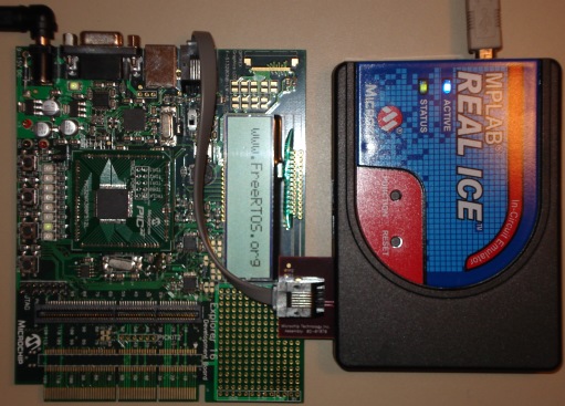 Explorer 16 with PIC32 PIM
|
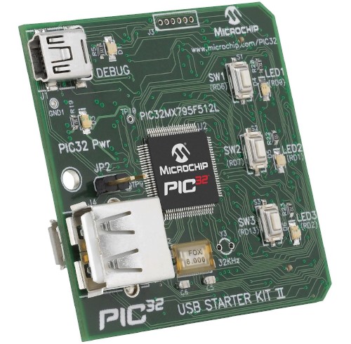 PIC32 USB II Start Kit
|
Introduction
The PIC32MX RTOS port
This page presents the FreeRTOS port and demo application for the PIC32MX -
a 32bit microcontroller from Microchip
that has a MIPS M4K core.
The FreeRTOS PIC32MX port:
-
Provides a full interrupt nesting model.
-
Never completely disables interrupts - although the MIPS core does itself
disable interrupts when it enters an exception, interrupts are quickly re-enabled
by the RTOS code inside the exception handler.
-
Maintains a separate interrupt stack. This ensures stacks allocated to
RTOS tasks do not each need to include adequate space to hold a complete,
and potentially nested, interrupt stack frame.
-
Supports interrupt stack overflow detection in addition to the standard
task stack overflow detection. Interrupt stack overflow detection is
turned on by building with
configCHECK_FOR_STACK_OVERFLOW set to 3 when
configASSERT() is also defined.
FreeRTOS is an integral part of MPLAB Harmony - Microchip's integrated driver and
middleware package. An older application note
(and source code) is also available from the Microchip web site that shows how to
integrate FreeRTOS with Microchip's now legacy peripheral and middleware libraries.
The demo application
MPLAB X and
MPLAB XC32
are now the preferred IDE and compiler respectively with which to build the FreeRTOS demos. MPLAB 8
projects are still included in the RTOS source code download, but will be retired
at some time in a future release.
Pre-configured support for multiple PIC32 derivatives and hardware platforms is
provided by the provision of multiple build configurations within the MPLAB X
project. Build configurations are provided for:
-
A PIC32MX360F512 PIM on the Explorer 16 evaluation board.
-
A PIC32MX460F512L PIM on the Explorer 16 evaluation board.
-
A PIC32MX795 PIM on the Explorer 16 evaluation board.
-
The PIC32 USBII Starter Kit (also fitted with a PIC32MX795).
The MPLAB 8 project is pre-configured to target the PIC32MX360 microcontroller running on an
Explorer 16 evaluation board.
Each build configuration can be used to build either a simple blinky demo or a
comprehensive test and demo application. The comprehensive application demonstrates
and tests the interrupt nesting behaviour. Build instructions are provided on this
page.
IMPORTANT! Notes on using the PIC32 RTOS port
Please read all the following points before using this RTOS port.
- Source Code Organization
- The Demo Application
- Configuration and Usage Details
See also the FAQ My application does not run, what could be wrong?
Source Code Organization
The FreeRTOS download contains the source code for all the FreeRTOS ports, so
contains many more files than used by the PIC32 demo.
See the Source Code Organization section for a description of the
downloaded files, and information on creating a new project.
The MPLAB 8 demo application workspace for the PIC32MX / MIPS port is called
RTOSDemo.mcw, and is located in the FreeRTOS/Demo/PIC32MX_MPLAB directory.
The MPLAB X project is called RTOSDemo.X, and is located off of the same directory.
The Demo Application
Demo application hardware setup - Explorer 16
All the Explorer 16 jumpers can remain in their default positions - in particular, JP2 should be fitted to ensure correct operation of the LEDs.
The demo application includes tasks that send and receive characters over UART2. The characters sent by one task are received by another - with an error condition
being flagged if any characters are missed or received out of order. A loopback connector is required on the Explorer16 9way D socket for this mechanism to
operate (pins 2 and 3 should be connected together). The internal loopback mode of the UART itself is not used by default.
NOTE: The UART interrupt service routine (ISR) uses an RTOS queue to send
individual characters from the ISR to an RTOS tasks, and a separate RTOS queue to
send individual characters from an RTOS task into the ISR. Using queues to send
individual characters in this way is very inefficient. The provided UART driver
is intended to demonstrate queues being used from an ISR and to stress test the
RTOS port. It is not intended to represent an efficient interrupt implementation.
Functionality
The demo application can be configured to provide very simply 'blinky' style
functionality, or a full and comprehensive test and demonstration of a subset of RTOS
features. The mainCREATE_SIMPLE_BLINKY_DEMO_ONLY constant, which is
#define(d) at the top of main.c, is used to switch between the two.
Demo application tasks are split between standard demo tasks, and demo specific
tasks. Standard demo tasks are used by all FreeRTOS port demo applications.
They have no purpose other than to demonstrate the FreeRTOS API, and test a port.
When mainCREATE_SIMPLE_BLINKY_DEMO_ONLY is set to 1
When mainCREATE_SIMPLE_BLINKY_DEMO_ONLY is set to 1 main() calls main_blinky().
main_blinky() creates a very simple example that uses two
tasks, one queue, and one software timer.
-
The Blinky Software Timer:
This demonstrates an auto-reload software timer. The timer callback
function does nothing but toggle an LED.
-
The Queue Send Task:
The queue send task is implemented by the prvQueueSendTask() function.
prvQueueSendTask() just sits in a loop, sending the value 100 to the queue
every 200 milliseconds.
-
The Queue Receive Task:
The queue receive task is implemented by the prvQueueReceiveTask()
function. prvQueueReceiveTask() sits in a loop blocking on attempts to
read from the queue (no CPU cycles are consumed while it is blocked),
toggling an LED each time a value is received. The queue send task
writes to the queue very 200 milliseconds, so the queue receive task
will unblock and toggle the LED every 200 milliseconds.
When mainCREATE_SIMPLE_BLINKY_DEMO_ONLY is set to 0
When mainCREATE_SIMPLE_BLINKY_DEMO_ONLY is set to 0 main() calls main_full().
main_full() creates a very comprehensive test and demo application that
creates numerous RTOS tasks and software timers. The demo will execute on both
the Explorer 16 and the USB II Starter Kit, although when on the starter kit the
LCD and UART tasks are not used (as they are not available on the hardware) and
fewer flash tasks are created to allow the 'check timer' (described below) access
to one of the three LEDs available on the Starter Kit hardware.
The description below is correct when the demo is executed on the Explorer 16.
-
LEDs marked D3 to D5 are under control of the 'flash' software
timers. Each will flash at a constant frequency, with LED D3 being
the fastest and LED D5 being the slowest.
-
LED D7 will toggle each time a character is transmitted on
the serial port. The frequency is too high to
distinguish the individual toggles between characters,
but the spacing between complete message transfers is
perceptible. The delay between each message is pseudo
randomized for test purposes.
Note the PIC32MX795 demo does not include the serial port
test tasks because its UART IP is subtly different to that found on
the PIC32MX460 and PIC32MX360 parts.
-
LED D8 will flash each time a character is received and
validated on the serial port (through the loopback connector).
Again the frequency is too high to distinguish the individual
toggles.
-
Most of the tasks do not update an LED so have no visible
indication that they are operating correctly. Therefore a
'Check' software timer is created to monitor all the other tasks.
The check software timer callback monitors the system
operation every 3 seconds, then writes a PASS or FAIL message
to the LCD (via the LCD task). Any failures are latched, and
the message displayed indicates in which task the failure was
detected (this functionality can be tested by removing the
loopback connector while the demo is executing, and in so doing
deliberately creating an error in the UART loopback test tasks). If no
errors exist a PASS message is displayed that includes a
count value originating from a high frequency timer. The
high frequency timer interrupt executes at 20KHz, incrementing
the displayed value once every 20,000 interrupts. The
displayed value should therefore count in seconds. More
information on the high frequency timer is provided in the
RTOS Configuration and Usage
section of this page.
The check software timer callback also toggles LED D10. The
toggle frequency will increase if an error has been detected.
-
The application also demonstrates the use of a 'gatekeeper'
task, in this case an LCD gatekeeper. The LCD task is the
only task that is permitted to access the LCD directly. Other
tasks wishing to write a message to the LCD send the message
on a queue to the LCD task instead of accessing the LCD
themselves. The LCD task just blocks on the queue (so it does not
consume any CPU cycles) waiting
for messages - automatically unblocking and displaying the
messages as they arrive.
-
Interrupt nesting is exercised using one task and two
interrupts - all of which access the same two queues. The
two interrupts run at different priorities, and both run
above the RTOS kernel interrupt priority, meaning a maximum nesting
depth of three is demonstrated by this particular test. The
high frequency timer interrupt adds another nesting level. See the
RTOS Configuration and Usage
section for a more complete explanation of the executing
interrupts, and their respective priorities.
Building and debugging the demo application with MPLAB X
These instructions assume you have MPLAB X and the MPLAB XC32 compiler correctly
installed on your host computer.
-
Open the project from within the MPLAB X IDE (the location of
the project is detailed in the Source Code Organization section
near the top of this page).
-
Select the build configuration that matches your hardware
configuration. Three build configurations target the Explorer 16
hardware, and one the PIC32 USB II Starter Kit. The USB_II_STARTER_KIT
build configuration must be selected to use the Starter Kit as
the LED mappings are different.
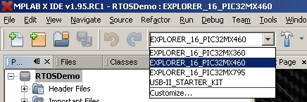 Selecting the build configuration in MPLAB
-
If the Explorer 16 is being used then
connect the ICD3 or Real ICE debugger interface to the Explorer
16 development board as described in the Explorer 16 manual.
If the USB II Starter Kit is being used then connect the Starter
Kit directly using the USB connector marked J1 on the Starter
Kit PCB.
-
From the IDE's 'Debug' menu, select 'Debug Project'. The project
should build without an errors or warnings, and the resultant
binary programmed into the PIC32 flash memory.
RTOS port specific configuration
Configuration items specific to this demo are contained in FreeRTOS/Demo/PIC32MX_MPLAB/FreeRTOSConfig.h. The
constants defined in that file can be edited to suit your application. In particular -
- configTICK_RATE_HZ
This sets the frequency of the RTOS tick. The supplied value of 1000Hz is
useful for testing the RTOS kernel functionality but is faster
than most applications require. Lowering this value will improve efficiency.
- configKERNEL_INTERRUPT_PRIORITY and configMAX_SYSCALL_INTERRUPT_PRIORITY
See the interrupt configuration
section of the RTOS kernel configuration documentation for full information on
these options.
configKERNEL_INTERRUPT_PRIORITY sets the interrupt priority used by the RTOS kernel
itself, and will normally be set to the lowest possible interrupt priority.
configMAX_SYSCALL_INTERRUPT_PRIORITY sets the highest interrupt priority
from which queue, software timer, and semaphore API functions can be called
(note that only API functions that end in FromISR() can be called from within
an ISR).
configKERNEL_INTERRUPT_PRIORITY should be set to the lowest priority.
Interrupts above configMAX_SYSCALL_INTERRUPT_PRIORITY will not be masked
by kernel critical sections and will therefore be unaffected
by RTOS kernel activity - within the limitations imposed by the hardware itself.
By way of demonstration, the demo application defines
configMAX_SYSCALL_INTERRUPT_PRIORITY to be 3, configKERNEL_INTERRUPT_PRIORITY to be 1,
and all other interrupts as follows:
-
The UART is allocated a priority of 2. This means it can interrupt
the RTOS tick, and can also safely use interrupt safe queue functions.
-
Two timers are configured to generate interrupts just to test the
nesting and queue access mechanisms. These timers are allocated
priorities 2 and 3 respectively. Even though they both access the
same two queues, the priority 3 interrupt can safely interrupt the
priority 2 interrupt. Both can interrupt the RTOS tick.
-
Finally, a high frequency timer interrupt is configured to use
priority 4 - therefore kernel activity will never prevent the high
frequency timer from executing immediately that the interrupt is
raised (within the limitations of the hardware itself). It is
not safe to access a queue from this interrupt, even using interrupt
safe RTOS API functions, because it is above configMAX_SYSCALL_INTERRUPT_PRIORITY.
Each port #defines 'BaseType_t' to equal the most efficient data type for that
processor. This port defines BaseType_t to be of type long.
Note that vPortEndScheduler() has not been implemented.
Interrupt service routines
Interrupt service routines that cannot nest have no special requirements and can
be written as per the compiler documentation. However interrupts written in this
manner will utilise the stack of whichever task was interrupted, rather than the
system stack, necessitating that adequate stack space be allocated to each
created task. It is therefore not recommended to write interrupt service routines
in this manner.
Interrupts service routines that can nest require a simple assembly wrapper, as
demonstrated below. It is recommended that all interrupts be written in this manner.
The UART interrupt within the PIC32 demo can be used as an example - an outline
of the assembly code wrapper for which is shown in Listing 1, and an outline
of the corresponding C function handler is shown in Listing 2:
/* Prototype to be included in a C file to ensure the vector is
correctly installed.  Note that because this ISR uses the FreeRTOS
assembly wrapper the IPL setting in the following prototype has no
effect.  The interrupt priority is set using the ConfigIntUART2()
PIC32 peripheral library call. */
void __attribute__( (interrupt(ipl1), vector(_UART2_VECTOR)))
                                                    vU2InterruptWrapper( void );


/* Header file in which portSAVE_CONTEXT and portRESTORE_CONTEXT are defined. */
#include "ISR_Support.h"

/* Ensure correct instructions is used. */
.set	nomips16
.set 	noreorder

/* Interrupt entry point. */
vU2InterruptWrapper:

  /* Save the current task context.  This line MUST be included! */
  portSAVE_CONTEXT

  /* Call the C function to handle the interrupt. */
  jal vU2InterruptHandler
  nop

  /* Restore the context of the next task to execute.  This line
  MUST be included! */
  portRESTORE_CONTEXT

  .end  vU2InterruptWrapper
Listing 1: Assembly code wrapper for handling an interrupt that can cause a context switch
Some notes on the assembly file wrapper:
-
I have found that the assembly file in which the wrapper is placed must
have a .S extension (with a capitol S). Using a lower case .s may
result in the portSAVE_CONTEXT and portRESTORE_CONTEXT macros being
incorrectly inlined.
-
The portSAVE_CONTEXT and portRESTORE_CONTEXT macros must be used as the
very first and very last executable lines in the function respectively.
-
When the FreeRTOS assembly file wrapper is used as an entry point the
IPL setting in the ISR function prototype has no effect.
Second, the C function called by the assembly file wrapper:
        void vU2InterruptHandler( void )
        {
        /* Declared static to minimise stack use. */
        static BaseType_t xYieldRequired;

            xYieldRequired = pdFALSE;

            /* Are any Rx interrupts pending? */
            if( mU2RXGetIntFlag() )
            {
                /* Process Rx data here. */

                /* Clear Rx interrupt. */
                mU2RXClearIntFlag();
            }

            /* Are any Tx interrupts pending? */
            if( mU2TXGetIntFlag() )
            {
                /* Process Tx data here. */

                /* Clear Tx interrupt. */
                mU2TXClearIntFlag();
            }

            /* If sending or receiving necessitates a context switch, then switch
            now. */
            portEND_SWITCHING_ISR( xYieldRequired );
        }
Listing 2: The C portion of an ISR that can cause a context switch
Some notes on the C function:
-
If portEND_SWITCHING_ISR() is called, it must be called as the very last line within the C
function.
-
The parameter passed to portEND_SWITCHING_ISR() should be zero if no
context switch is required, and non zero if a context switch is required.
Performing a context switch from inside an interrupt can result in the
interrupt returning to a task other than the task originally interrupted.
-
The C function does not use any special qualifiers or attributes - it is
just a standard C function.
See the full UART interrupt handler within the PIC32 demo application for a
complete example - note however that, as downloaded, the UART driver is intended
to generate lots of interrupts (with the intention of testing the robustness of
the MIPS port) and should therefore not be regarded as an optimal solution.
Critical sections
Exiting a critical section will always set the interrupt priority such that all interrupts are enabled, no matter what its level when the critical section
was entered. FreeRTOS API functions themselves will use critical sections.
Execution context
In line with the conventions documented in the XC32 compiler manual, the RTOS
kernel assumes all access to the K0 and K1 registers will be atomic. Code generated
by the XC32 compiler conforms to this convention so if you are writing application purely in C then this is of no concern.
Care must be taken however if any hand written assembly code is used to ensure that that too conforms to the same convention.
Shadow registers
The interrupt shadow registers are not used and are therefore available for use by the host application. Shadow registers should not be used within an interrupt
service routine that causes a context switch.
Software interrupts
The RTOS kernel makes use of the MIPS software interrupt 0. This interrupt is therefore not available for use by the application.
Switching between the pre-emptive and co-operative RTOS kernels
Set the definition configUSE_PREEMPTION within FreeRTOS/Demo/PIC32MX_MPLAB/FreeRTOSConfig.h to 1 to use pre-emption or 0
to use co-operative. The demo application will only execute correctly with configUSE_PREEMPTION set to 0 if configIDLE_SHOULD_YIELD is set to 1.
Compiler options
As with all the ports, it is essential that the correct compiler options are used. The best way to ensure this is to base your
application on the provided demo application files.
Memory allocation
Source/Portable/MemMang/heap_4.c is included in the PIC32 demo application project to provide the memory
allocation required by the RTOS kernel.
Please refer to the Memory Management section of the API documentation for
full information.
Serial port driver
It should also be noted that the serial drivers are written to test some of the real time kernel features - and they are not
intended to represent an optimized solution. In particular, they make heavy use of the queue mechanism and do not use the available FIFO or DMA.