Xilinx PowerPC PPC440 Port
on a Virtex5 FPGA
[RTOS Ports]
The PPC440 port was developed using the
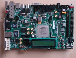
PowerPC & MicroBlaze Virtex-5 Embedded Development Kit. This is a very comprehensive kit that
includes:
- An ML507 development board (instructions are provided should you wish to use an alternative development board).
- All the required hardware development tools.
- All the required software development tools (EDK and ISE).
- A USB JTAG interface.
- All the required cables.
IMPORTANT! Notes on using the Virtex5 PowerPC RTOS port
Please read all the following points before using this RTOS port.
- Source Code Organization
- The Demo Application
- Configuration and Usage Details
See also the FAQ My application does not run, what could be wrong?
Source Code Organization
The FreeRTOS download contains the source code for all the FreeRTOS ports so contains many more files than used by this demo.
See the Source Code Organization section for a description of the
downloaded files and information on creating a new project.
Three Platform Studio project configurations are provided, all of which are called system.xmp:
-
A project that does not include a floating point unit can be located in the FreeRTOS/Demo/PPC440_Xilinx_Virtex5_GCC directory.
-
A project configured to use a single precision floating point unit can be located in the FreeRTOS/Demo/PPC440_SP_FPU_Xilinx_Virtex5_GCC
directory.
-
A project configured to use a double precision floating point unit can be located in the FreeRTOS/Demo/PPC440_DP_FPU_Xilinx_Virtex5_GCC
directory.
The Demo Application
Each demo application creates at least 40 static real time tasks and then continuously creates and deletes another two. Most of these
tasks are from the set of standard demo tasks and are not specific to the PPC440/Virtex5 application - they exist purely to test
the port and provide examples of how each FreeRTOS API function can be used.
The demo application section of this site provides more information on the
standard demo tasks.
In addition to the standard demo tasks the follow demo specific tasks are created:
Demo application hardware setup
The demo application includes the ComTest tasks - where one task transmits RS232 characters to another. For correct operation
of this task a loop-back connector must be fitted to ML507 connector labeled COM1 (pins 2 and 3
must be connected together on the 9Way connector).
The demo application uses LEDs that are built onto the development board so no other hardware setup is needed.
Functionality
When executing correctly the demo application will behave as follows:
-
LEDs 0, 1 and 2 are under control of the 'flash' tasks. Each will flash at a constant frequency, with LED 2 being
the fastest and 0 being the slowest.
-
LED 3 is under control of the 'Check' task and should toggle every 3 seconds. It the LED toggles every 500ms then at least
one error has been discovered and latched (this mechanism can be tested by removing the loopback connector from COM1,
and in doing so deliberately generating an error).
Generating and downloading the bitstream
The Xilinx Platform Studio project is aware of the dependencies between each component of the build. If you attempt to download
a bitstream it will first check that all components of the bitstream are up to date, and if not ensure they are built in the correct
order. The easiest way of performing a complete build is therefore to select "Download Bitstream" from the Platform Studio
"Device Configuration" menu:
-
Connect the ML507 development board to the host computer using the USB JTAG adaptor.
-
Power up the ML507.
-
Open the relevant system.xmp files from within the Platform Studio IDE.
-
Select "Download Bitstream" from the Platform Studio "Device Configuration" menu. The initial build can take a long time to complete, depending
on the host PC and the configuration being created. Once complete the bitstream will be downloaded to the ML507.
The software project is executed from RAM so will be lost if power is removed.
Building the demo application
The demo application and all dependent libraries can be build by selecting "Build All User Applications" from the Platform Studio "Software"
menu. The application should build without any errors or warnings.
Using the debugger
Once the FPGA has been programmed, software builds can be modified and executed using the Insight debugger:
- Start the XMD interface by selecting "Launch XMD" from the Platform Studio "Debug" menu.
This is necessary for the host debugger to communicate with the development board.
- In the XMD console window
type "dow RTOSDemo/executable.elf" to download the elf file, followed by "con" [continue] to start the application executing.
- Start the Insight debugger by selecting "Launch Software Debugger" from the Platform Studio "Debug" menu.
- From within the Insight IDE, select "Connect to Target" from the "Run" menu. A dialog box will appear the first time a connection is attempted
- ensure the configuration shown in the dialog is as per the
following image:
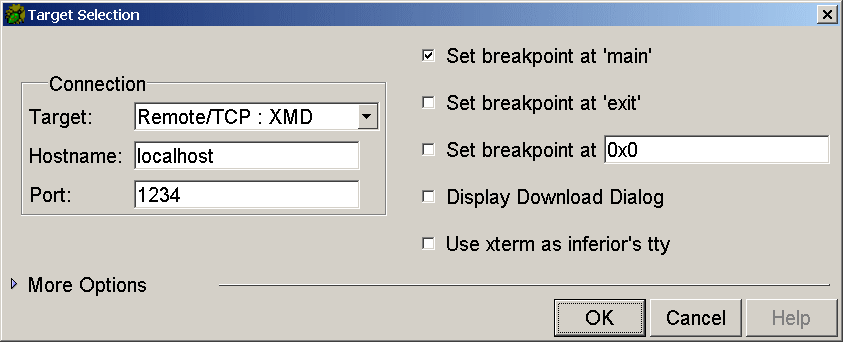 Insight target settings
- Insight will connect to the target. From
then on Insight can be used to step through the code and inspect system resources as normal.
Initialising the interrupt controller
vPortSetupInterruptController() must be called prior to either the installation of any interrupt
service routines or vTaskStartScheduler() being called. The demo application called vPortSetupInterruptController()
as the first line within main(). vPortSetupInterruptController() has the following prototype:
void vPortSetupInterruptController( void );
Installing an interrupt handler
Interrupt handlers should be installed using xPortInstallInterruptHandler(). The source file serial.c includes an example usage of the function.
xPortInstallInterruptHandler() has the following prototype:
BaseType_t xPortInstallInterruptHandler( unsigned char ucInterruptID,
                                            XInterruptHandler pxHandler,
                                            void *pvCallBackRef );
Where:
-
ucInterruptID is the ID assigned to the peripheral within the Xilinx generated "xparameters.h" header file.
For example, in the RTOS demo application the ID XPAR_OPB_INTC_0_RS232_UART_INTERRUPT_INTR is assigned to the UART.
-
pxHandler is a pointer to a C interrupt handler function.
-
pvCallBackRef is a pointer to the parameter that will be passed into the C interrupt handler function.
Interrupt handler functions must accept a single void * parameter - even if this parameter is not used.
The function vSerialISR() within serial.c can be used as an example.
Maths libraries
The (emulated floating point) maths libraries supplied with GCC are not re-entrant and must not be used without taking appropriate mutual exclusion precautions.
It is preferable therefore to make use of the floating point unit as described below.
Project settings required in order to use the APU Floating Point Unit
These are the relevant settings:
- configUSE_FPU is set to 1 within FreeRTOSConfig.h. If the double precision floating point unit is being used then USE_DP_FPU must also be defined
(the double precision example included in the download does this as a command line option).
- configUSE_APPLICATION_TASK_TAG is set to 1 within FreeRTOSConfig.h.
- FreeRTOSConfig.h contains the line #include "FPU_Macros.h". FPU_Macros.h contains the required traceTASK_SWITCHED_IN() and
traceTASK_SWITCHED_OUT() definitions. The include file ordering is critical - including FPU_Macros.h from within FreeRTOSConfig.h
ensures the order is correct.
- Incorporating the APU FPU into your FPGA design should automatically set the compiler options to be correct for hardware as
opposed to emulated floating point operation, "-mfpu=sp_full" being the required option.
Specifying that a task uses floating point operations
The best way to familiarize yourself with the floating point requirements is to view the examples provided within
FreeRTOSRTOS/Demo/PPC440_DP_FPU_Xilinx_Virtex5_GCC/RTOSDemo/flop/flop.c and FreeRTOS/Demo/PPC440_DP_FPU_Xilinx_Virtex5_GCC/RTOSDemo/flop/flop-reg-test.c
(and their single precision equivalents).
This sub-section provides a brief explanation of the code.
Associated with each task is a tag value. This is not used by the RTOS kernel itself so can be used by either the port layer or the
application for any purpose it wishes. The port described by this page uses the tag value to indicate whether or not the task
requires a floating point context. The traceTASK_SWITCHED_OUT() and traceTASK_SWITCHED_IN() macros are defined to perform the
actual floating point context saving and restoring respectively.
The tag value must either be NULL or point to a buffer that is large enough to hold the floating point context. NULL is the default
when a task is created and indicates that the task does not require a floating point context.
The function:
void vTaskSetApplicationTaskTag( TaskHandle_t xTask, TaskHookFunction_t pxTagValue );
is used to associate a tag value of pxTagValue with the task whose handle is equal to xTask.
The constant portNO_FLOP_REGISTERS_TO_SAVE indicates how many 32bit registers make up the floating point context.
As an example, a buffer large enough to hold a single precision floating point context can be allocated using:
float fFlopContext[ portNO_FLOP_REGISTERS_TO_SAVE ];
Changing float to double would allocate enough space to hold a double precision floating point context.
This buffer can then be assigned to the tag value of a task using the following call:
vTaskSetApplicationTaskTag( xTask, ( void * ) ulFlopContext );
Again, please refer to the provided examples.
RTOS port specific configuration
Configuration items specific to this port are contained in FreeRTOSConfig.h. All three supplied PPC440 demos have their own FreeRTOSConfig.h
file within their respective project directories. The
constants defined in this file can be edited to suit your application. In particular - the definition
configTICK_RATE_HZ is used to set the frequency of the RTOS tick. The supplied value of 1000Hz is useful for
testing the RTOS kernel functionality but is faster than most applications require. Lowering this value will improve efficiency.
Each port #defines 'BaseType_t' to equal the most efficient data type for that processor. This port defines
BaseType_t to be of type long.
Note that vPortEndScheduler() has not been implemented.
Requesting a context switch within an ISR
The macro portYIELD_FROM_ISR() can be called from within an ISR to request that a new task be selected to run prior to the ISR terminating.
This would normally be done where the ISR caused a task to unblock - and the unblocked task has a priority higher than the currently
executing task.
Switching between the pre-emptive and co-operative RTOS kernels
Set the definition configUSE_PREEMPTION within Demo/MicroBlaze/FreeRTOSConfig.h to 1 to use pre-emption or 0
to use co-operative.
Compiler options
As with all the ports, it is essential that the correct compiler options are used. The best way to ensure this is to base your
application on the provided demo application files.
Memory allocation
Source/Portable/MemMang/heap_2.c is included in the PowerPC demo application to provide the memory
allocation required by the RTOS kernel.
This is a very basic scheme that allocates memory blocks from a large array. The size of the array is set by the constant configTOTAL_HEAP_SIZE within FreeRTOSConfig.h.
Please refer to the Memory Management section of the API documentation for
full information.
Serial port driver
It should also be noted that the serial port driver is written to demonstrate and test some of the real time kernel features - and is not intended to represent an optimized solution.
NOTE: The baud rate used by the basic UART is fixed once the hardware image has been generated. The baud rate parameter
passed to the serial port initialisation routine has no effect.