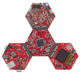
Pre-configured projects are provided for each of the following ARM Cortex-M4 compilers:
Each of the four projects contains three build configurations, one build configuration targeting one of the following XMC4000 Hexagon Application Kits:
Each build configuration can be compiled to create either a simple blinky demo, or a comprehensive test and demo application. Build instructions are provided below.
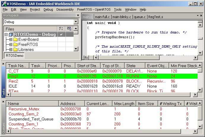
Note 1: The projects in the FreeRTOS download include special settings to
workaround an XMC4000 silicon errata. Please see the
build instructions for the
individual compilers below for more information.
Note 2: The IAR project will fail to build and be corrupted (so it can no longer be used with any IAR version) if it is opened in a version of EWARM that is older than the version that was used to originally create the project.
See also the FAQ My application does not run, what could be wrong?
The demo uses the LED built onto each Hexagon Application Kit board, so no hardware setup is required.
The XMC4200 and XMC4400 Hexagon kits have a built in J-Link debugger interface. These boards can be connected directly to the host computer using a USB cable with no other connections required. These Hexagon boards each have two USB connectors, so be careful to use the one marked "Debug USB".
The XMC4500 Hexagon kit does not have a build in J-Link, and therefore requires two connections:
Connect an external debugger interface between the host computer and one of the two debug ports provided on the XMC4500 Hexagon PCB. As supplied the projects are configured to use a J-Link, so the use of any other compatible device will require the project options to be updated as appropriate.
Connect a USB cable between the USB OTG connector on the XMC4500 Hexagon PCB and any convenient USB host.
The following sub-sections provide instructions on using each of the four supported ARM Cortex-M4 compilers.
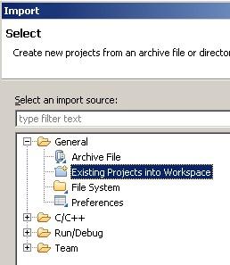
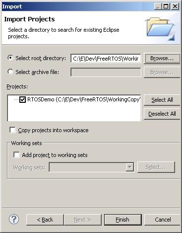
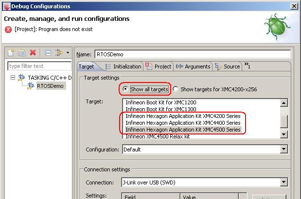
Note: At the time of writing each build configuration within a DAVE project must target the exact same microcontroller part number. The delivered build configurations are however configured to selectively include and exclude chip specific files, so the projects will be built correctly, although an additional step is required when starting a debug session; Check the Debug launch configuration to ensure it is configured to target the hardware actually being used (see image below). It is likely that the debugger will also issue a warning when a debug session is launched - the warning can be ignored providing the launch configuration is configured correctly for the hardware in use.
main() calls main_blinky():
main_blinky() creates a queue, a queue send task, and a queue receive task, before starting the scheduler.
The queue send task is implemented by the prvQueueSendTask() function in main_blinky.c.
prvQueueSendTask() sends the value 100 to the queue every 200 milliseconds.
The queue receive task is implemented by the prvQueueReceiveTask() function in main_blinky.c.
prvQueueReceiveTask() blocks to wait for data to arrive on the queue. Each time the value 100 is received from the queue it toggles the LED. As data is sent to the queue every 200ms, the LED will toggle every 200ms.
main() calls main_full():
main_full() creates a set of standard demo tasks, some application specific test tasks, and a timer, before starting the scheduler.
The reg test tasks test the context switching mechanism by filling each MCU register with a known value, then continuously checking that each register maintains its expected value for the lifetime of the task.
The "Check" software timer monitors the status of all the other tasks in the system, looking for a task either stalling or reporting an error. It toggles an LED each time it is called.
If the LED is toggling every three seconds then the check task has not detected any stalled tasks or received any error reports. If the LED is toggling every 200ms then at least one error has been found.
Note that portEND_SWITCHING_ISR() will leave interrupts enabled.
An example interrupt handler called Dummy_IRQHandler() is provided at the end of main.c as a reference implementation. Dummy_IRQHandler() is also replicated below.
void Dummy_IRQHandler(void)
{
long lHigherPriorityTaskWoken = pdFALSE;

    /* Clear the interrupt if necessary. */
    Dummy_ClearITPendingBit();

    /* This interrupt does nothing more than demonstrate how to synchronise a
    task with an interrupt.  A semaphore is used for this purpose.  Note
    lHigherPriorityTaskWoken is initialised to zero. Only FreeRTOS API functions
    that end in "FromISR" can be called from an ISR! */
    xSemaphoreGiveFromISR( xTestSemaphore, &lHigherPriorityTaskWoken );

    /* If there was a task that was blocked on the semaphore, and giving the
    semaphore caused the task to unblock, and the unblocked task has a priority
    higher than the current Running state task (the task that this interrupt
    interrupted), then lHigherPriorityTaskWoken will have been set to pdTRUE
    internally within xSemaphoreGiveFromISR().  Passing pdTRUE into the
    portEND_SWITCHING_ISR() macro will result in a context switch being pended to
    ensure this interrupt returns directly to the unblocked, higher priority,
    task.  Passing pdFALSE into portEND_SWITCHING_ISR() has no effect. */
    portEND_SWITCHING_ISR( lHigherPriorityTaskWoken );
}
Attention please!: See the page dedicated to setting interrupt priorities on ARM Cortex-M devices. Remember that ARM Cortex-M cores use numerically low priority numbers to represent HIGH priority interrupts. This can seem counter-intuitive and is easy to forget! If you wish to assign an interrupt a low priority do NOT assign it a priority of 0 (or other low numeric value) as this will result in the interrupt actually having the highest priority in the system - and therefore potentially make your system crash if this priority is above configMAX_SYSCALL_INTERRUPT_PRIORITY. Also, do not leave interrupt priorities unassigned, as by default they will have a priority of 0 and therefore the highest priority possible.
The lowest priority on a ARM Cortex-M core is in fact 255 - however different ARM Cortex-M microcontroller manufacturers implement a different number of priority bits and supply library functions that expect priorities to be specified in different ways. For example, on Infineon ARM Cortex-M4 microcontrollers, the lowest priority you can specify is in fact 63 - this is defined by the constant configLIBRARY_LOWEST_INTERRUPT_PRIORITY in FreeRTOSConfig.h. The highest priority that can be assigned is always zero.
It is also recommended to ensure that all priority bits are assigned as being preemption priority bits, and none as sub priority bits, as they are in the provided demo.
Note that the following lines are included in FreeRTOSConfig.h to map the FreeRTOS interrupt handler function names onto the CMSIS interrupt handler function names. This allows the linker scripts provided by the compiler tool vendors to be used without modification.
	#define vPortSVCHandler      SVC_Handler
	#define xPortPendSVHandler   PendSV_Handler
	#define xPortSysTickHandler  SysTick_Handler
This sets the frequency of the RTOS tick interrupt. The supplied value of 500Hz is useful for testing the RTOS kernel functionality, but is faster than most applications require. Lowering this value will improve efficiency.
Each port #defines 'BaseType_t' to equal the most efficient data type for that processor. All ARM Cortex-M4F ports define BaseType_t to be of type long.
Note that vPortEndScheduler() has not been implemented.