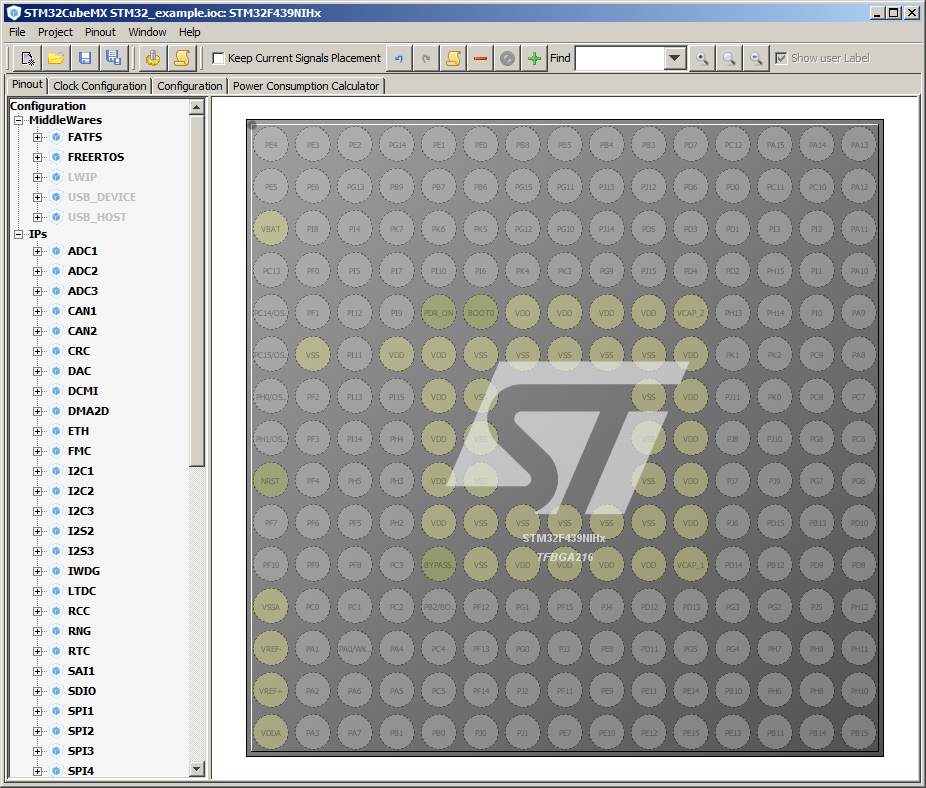
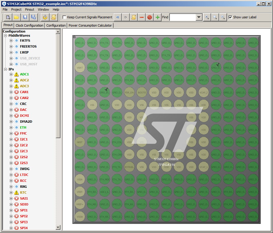
Main window, Pinout tab, with no pins assigned
Click to enlarge
The right pane of the Pinout tab displays an image of the selected STM32 ARM Cortex-M MCU. In this example a BGA part was selected, so the image shows all the pins on the BGA part. The main graphic at the top right of this page shows how the Pinout tab looks when an LQFP part number is selected. Hovering the mouse over a pin displays the possible assignments for that pin.
If the project was created by selecting an STM32 ARM Cortex-M part number and package then no pins will yet be assigned.
If the project was created by selecting an STM32 evaluation board (eval, STM32 Nucleo, etc.) then the pins will already be assigned to be correct for the selected hardware.
The top of the left pane of the pinout tab displays the middleware available for use on the selected part. The bottom of the left pane of the pinout tab displays the drivers available for use on the selected part.
Note that, by default, FreeRTOS is already available for selection (it is not greyed out), but lwIP (the TCP/IP stack) is not available for selection (it is greyed out). This is because, by default, none of the peripherals are yet enabled, and the STM32CubeMX software knows that lwIP cannot be selected unless the Ethernet peripheral has first been enabled. The work flow steps below demonstrate how to enable peripherals, including the Ethernet hardware, and the effect of doing so on the availability of pins and other peripherals.
STM32CubeMX searches for the pinout configuration that best suites the set of selected peripherals. Pin assignments can be fixed by checking the "Keep Current Signal Placement" check box, which is located in the menu bar. Pin assignments can also be made manually by clicking on a pin in the right pane, then selecting an assignment for that pin from the drop down list (this latter method is only recommended for advanced users).
| Click images to enlarge | |||
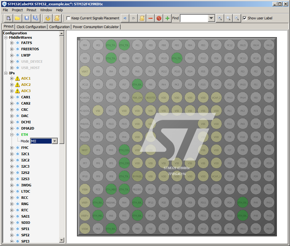
Configuring ETH for MII |
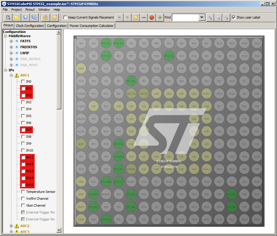
ADC input options after ETH selection |
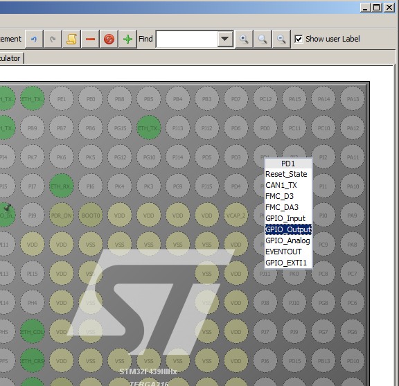
Manually assigning a pin from a drop down list |
The view after all unused pins are set to GPIO |
>>
On to step five
<<
Back to the STM32CubeMX practical walk-through index